
Disclaimer: This mod was tested by the writer of this post. Please try it at your own risk. RetroRGB.com (or any of its writers) aren’t responsible for any damage you do to your tools or VMU.
While this mod is fairly simple in concept, it is one of the fiddliest mods you might come across. As such, it requires patience and maybe more time than you would think. In addition, it will require some tricky detailed soldering (wires on the SMD LEDs). That being said, the results are spectacular! Using this method will give you a very evenly illuminated screen; this comes in clutch for checking your life meter while playing Resident Evil: Code Veronica in a nice, dark room. 😊
Enjoy!
Parts and tools required:
- A VMU.
- A Nintendo DS Lite backlight (can be harvested fairly simply from a broken NDSL, or purchased pretty cheap on ebay).
- A good soldering station with a sharp tip
- Good quality solder
- Good quality flux
- Kynar Wire
- A 75ohm–500ohm resistor (this is preference depending on how bright you want the screen, I went with a 333ohm SMD resistor I had on hand)
- Sharp Scissors
- Craft knife
- High percentage Isoproply Alcohol
- Q-Tips
- Microfiber Cloth
- A power supply with adjustable voltage and wire connections.
- PATIENCE!!
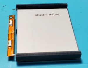
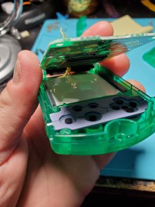
First, completely disassemble the VMU. It’s very basic, but if you need any help, a thorough guide with pictures can be found here. Note: it makes more sense to desolder the speaker than to peel it from the shell. This will keep it completely out of your way.
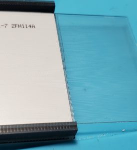
The DS Lite backlight, conveniently, is exactly double the size we need for this mod. In other words, one backlight can do two VMUs. However, for my unit at least, the polarizer had to be aligned diagonally, meaning I could only get a polarizing square for one VMU, but more on that later.
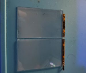
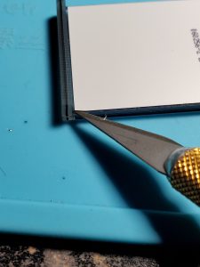
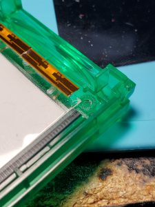
So next, we cut the clear backlight dispersion layer in half (it’s the clear plastic piece with the LEDs glued to it). One could use a craft knife, but I found this was easiest to do by marking it down the middle (with that craft knife) then just using a pair of sharp sheers to cut it in half.
Next, the backlight dispersion layer needs to be trimmed for length as well, and this is where the LCD can assist in alignment.
Again, mark it with a craft knife.
Luckily, accuracy is not critical here (you’ll see a wave in my line). The LCD has a bit of a ring around it that doesn’t display, so perfect sizing is really not necessary.
Again, cut with sheers.
Now place the backlight dispersion layer in the LCD And check to be sure you cut it correctly.
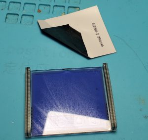
Now we can use the plastic dispersion panel to cut the other layers. HOWEVER, I do not advise cutting the polarizing layer just yet. Just cut the white backed reflector (looks like a mirror) and white diffusion (looks like a thin white sheet) layers.
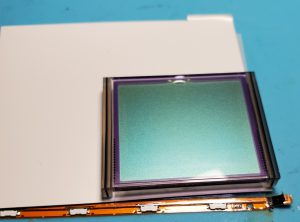
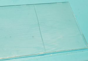
Next, we need to remove the stock backing to the LCD. Be VERY careful with this step as to not scratch the screen. We want to just grab the very edge of the plastic, just that bottom layer, and carefully lift that corner till we have something to grab onto. It is CRITICAL that we be careful not to damage the silicone edges on the LCD (these are the data connections). Take your time with this step, and it will come off pretty cleanly.
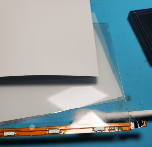
Once the backing layer is off, we will inevitably have some glue residue on the LCD. On my LCD, this cleaned up pretty easily.
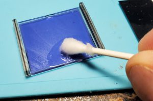
First, start with a Q-Tip saturated with isopropyl alcohol, and just wipe at the glue until it’s all gone.
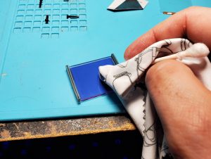
Then, to remove any leftover residue or streaking, wrap the Q-Tip in a microfiber cloth, then wipe the LCD till it is sparkling clean.
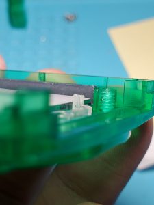
Next, we’ve got a bit of case trimming to do in order to accommodate the backlight panel. Here there are two little clear plastic posts that hold the LCD in place. The posts are on a little two-legged bracket that swivels on a central post. You can see it coming above the screen in the previous picture.
Cut those off till they are below the top of the LCD, but do not cut them completely off. See the picture for example cuts (again, perfection isn’t necessary here).
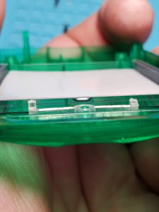
Next is one more cut to the plastic dispersion layer. You can see here that the plastic dispersion layer hits the screw posts. Just carefully cut off the corner on each side, then the dispersion layer will drop right in.
Now things get a bit fiddlier.
We need to cut the little flex cable the LEDs are mounted on so that we can wire them up in parallel and the series connection is severed. Again, scissors here are fine. Then, solder four small lengths of Kynar wire to both anodes and both cathodes. Inevitably, the glue that held the flex cable to the plastic layer will be eaten away by the flux and soldering. You can either use a small bit of glue to place the LEDs back where they came from, or a small amount of tape. I used a spray on adhesive.
I did find that alignment of the LEDs to the dispersion layer wasn’t really critical either, so don’t drive yourself crazy trying to make it perfect.
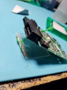
Next, feed the four wires through the little space in the middle of the VMU connector.
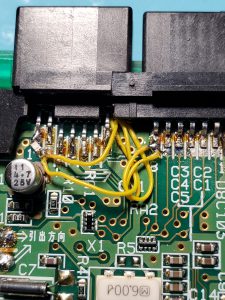
Now solder up the wires. Both anodes go to Pin 1 if you want the backlight to only turn on while in the controller (recommended) or to pin 14 if you want it to be on always (not recommended because it stays on even when the VMU is asleep. One could install a switch somewhere, but I chose not to. To help with install, I recommend beginning by soldering the anode wires to pin 14 so we can easily power up the VMU and test the backlight. Once that’s done, we can add a resistor to pin 1 then move the anode wires from 14 to the other end of the resistor. More on this later. Both cathodes go to either pins 7 or 8 (both ground). I left a bit of slack, and recommend this, as it will make it easier to have some wiggle room with alignment.
Now we need to determine polarizer alignment. I found the polarizer needed to be turned on a 45 degree angle to look correct. The screen should look clear and have good contrast while looking directly at it.
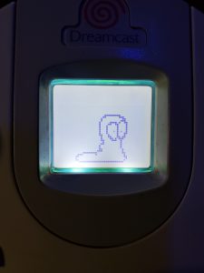
Without the correct orientation of the polarizer, things look very bad and washed out directly.
But then if you tilt it down, the contrast improves (the polarizer was backwards here, so the screen was inverted, but the point remains unchanged).
So now we’ll test to get the correct orientation. To do this test, place the reflective layer down first (against the PCB), then the plastic dispersion layer, then the white film, then place the LCD over it, lining up the connector edges to the points on the PCB. This takes some trial and error getting the LCD to line up, and you have to press gently on the edges to make sure solid contact is made. Next we need to power up the VMU. I used a universal power supply I had on hand, set to 6v, with the screw post wire end.
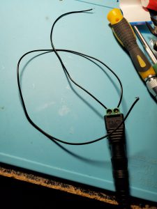
Solder these wires to the points where the battery clips make contact on the back of the VMU PCB.
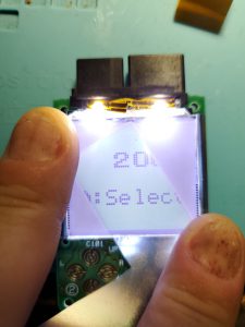
Now the VMU should power up, and you can slide a corner of the polarizing layer under the lcd, but above the white diffusion layer. If it looks like the example above, then we can confirm you need to cut the square with that orientation. Simply slide out the diffusion layer or the reflective layer and use it as a guide.
We’re in the home stretch now! it’s time to start lining the pieces up to reassemble. Place the LCD back in the front of the VMU, then place the polarizing layer in first (make sure it’s correctly oriented), followed by the diffusion layer, then the plastic dispersion layer, and finally the reflective layer. Carefully place the PCB back in, and reassemble! I suggest keeping the anode wires soldered to pin 14 for now to make testing easier. Close the case up, pop a couple batteries in, then check it out.
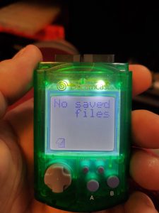
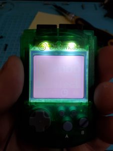
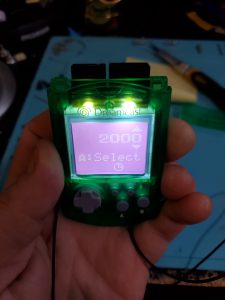
Hopefully it looks like this, and you can declare this mod a success!
If it does, simply remove the back cover of the case again, add a resistor to pin 1 (75-500ohms, I found 333ohm was perfect for my taste), then move the anode wires from pin 14 to the other end of the resistor. Solder the speaker back in place, and close the thing up once and for all!
Now slap that VMU in a controller, turn off all of the lights, and play some Dreamcast!