SNES Mini RGB Mod – DIY THS7316 RGB AMP
This mod shows you how to build your own RGB amp to bypass the SNES Mini’s internal amp. This isn’t necessary and you can simply use the SNES Mini’s built-in RGB encoder. This mod is just an alternative method. For more info, see the main SNES Mini RGB page.
If you’d like this mod performed for you, you can hire the following services:
Retrofixes SNES Mini RGB Mod – USA
Voultar’s SNES Mini RGB Mod – USA
Tools / Parts Needed:
You’ll need a few tools for this mod (more info on the tools can be found in the tools section):
– Soldering skills!
– SNES RGB cable.
– The 4.5mm tool that opens the SNES
– Philips head screwdriver
– Soldering iron / solder
– Thin gauge wire
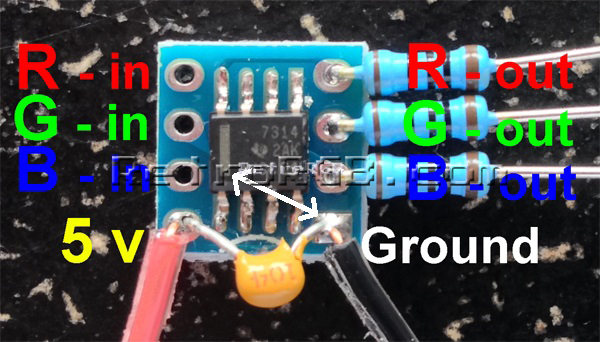
– RGB Amplifier chip, model # THS7316
– Circuit board to mount the RGB amp
Three 75 Ohm resistors, the lowest tolerance possible (also available from Digikey):
http://www.mouser.com/ProductDetail/Vishay/MRS25000C7509FRP00
– Three 1.2k resistors, the lowest tolerance possible (not available from Digikey):
http://www.mouser.com/ProductDetail/KOA-Speer/MF1-4DCT52R1201F
RGB Mod:
Please note: All pictures in this guide show the THS7314 amp, but I actually recommend you use the 7316 (installation is identical). The THS Amp Page will give you detailed information as to why, as well instructions on how to build the circuit.
– Start by assembling the RGB amp circuit. Also, here’s a trick: After you cut the excess pins from the resistors, save them for later in this guide!!!
– Next, open the console by removing the 4 screws on the bottom of the case (using the 4mm SNES tool) and remove the 7 philips screws from the board:
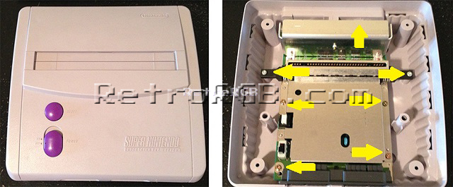
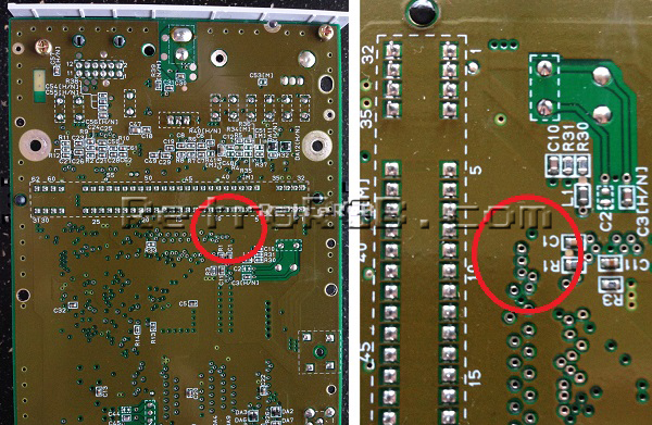
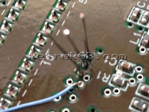
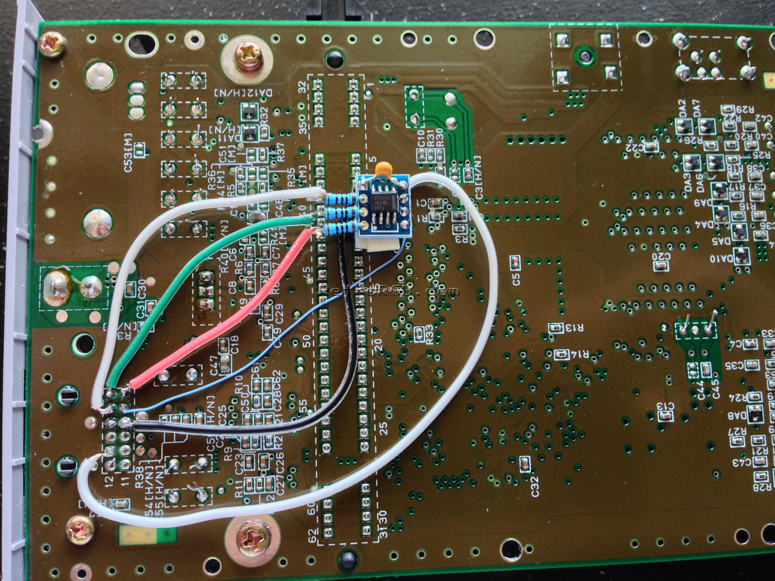
– Flip the board over and locate the following area:
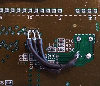
– Now for the tricky-but-cool part: Take the excess pins left over from the resistors and add them to the RGB holes. You’ll need to hold onto the pins with a pair of pliers or tweezers, as they’ll get really hot. Then, use your soldering iron to heat up each one individually until they slide through the board and stick out a bit. Afterwards, heat them again, adding a bit of solder to each side to secure them in place. Finally, carefully snip off any excess that’s sticking through the top (having some of the pin stick up is fine, as long as they aren’t touching anything else). It should now look like this on the bottom of the board (please ignore the wire in this picture, it was from another mod):
– I like to add two pieces of thick double-sided tape to the bottom of the RGB amp, as I find it makes a good cushion between the amp and the motherboard:
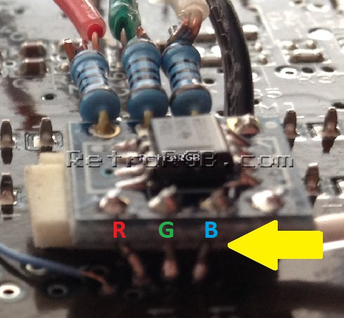
– Next, carefully slide the amp over the pins you just installed, solder them in place and cut any excess that’s sticking out. Make sure to align RGB on the amp, with RGB on the board:
– Also, make sure the components on the RGB amp aren’t touching anything on the motherboard (this is where the two pieces of thick double side tape come in handy):
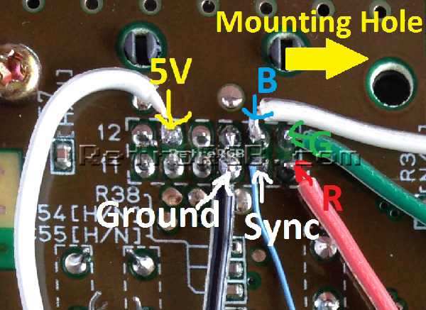
– Next, cut the wires down to size and solder them to the A/V port. There are other places on the board to find 5v and ground, however I find the A/V port easiest in this case as the pins are big. When you run the wires, be aware of the mounting hole, as you won’t want any of the wires to get pinched:
– The final installation should look like this; Please note that the blue wire in this picture is run to the wrong location (I’ll update the pics as soon as I have time). The SNES csync page shows the proper location (click for full-sized picture):
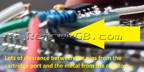
– Bolt everything back together and try it out. There should be plenty of clearance between the amp/wires and the bottom plastic, but be careful when putting it back, just in case.

Brightness Issues:
The output of the SNES Mini needs to be attenuated, otherwise the picture will be too bright and cause ringing. It’s an extremely easy mod:
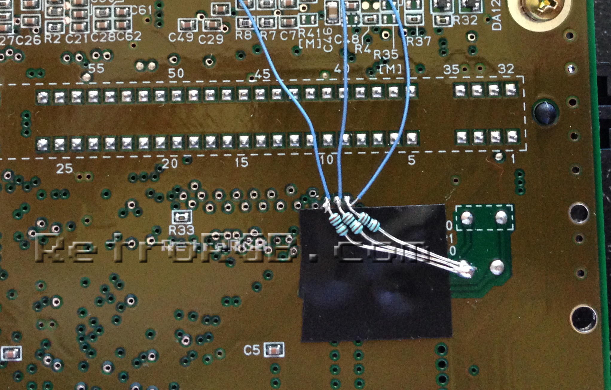
– First, solder the 1.2k Ohm resistors to the same places you’d get RGB from the board (if you used my mounting trick above, you can just solder the resistors to the RGB input pins on the THS circuit).
– Then, make sure to solder the RGB wires between the resistors and the board.
– Finally, the other side of all three resistors to ground (click for full-sized):
– I strongly recommend using shrink tubing on each resistor! I used tape to cover the components, but only because it made the above picture easier to see. For your installation it would be much better to shrink tube each one (thanks to John for his pic):
– For beginners, it must seem strange to tie all the video lines to ground, but as long as the video lines are on the motherboard-side of the resistor, it will work to properly adjust the input brightness to the exact level the SNES Mini should be outputting.
A note for SFC Jr owners: I suggest first trying the mod without the brightness-attenuating resistors. I’ve only personally tested one SFC Jr, but found that using the same resistors as the SNES Mini worked best. I’ve had other people report that no resistors at all is the best choice and Alex (aka ArcadeTV) said he needed these to get the proper output from his SFC Jr:
http://www.digikey.com/product-detail/en/MRS25000C7509FRP00/PPC75.0ZCT-ND/595092
If you’d like more detailed, technical information, here’s a link to the assembler games thread explaining all the details:
http://www.assemblergames.com/forums/showthread.php?53053-SNES-Mini-RGB-Measurements
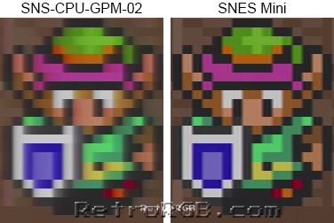
That’s it…not too hard of a mod and the picture quality is amazing!!! Check out the difference from an average (non-1CHIP) SNES 1 to a SNES Mini (there are many more pictures on the SNES Version Compare page):
When you’re done, feel free to go back to the main SNES page. If you’d like info on mods for other systems, head to the Getting RGB From Each System page or check out the main page for more retro-awesomeness.