The prestige of RGB has long been sought after by retro gamers. Unlike Europe and some other parts of the world, not all CRT TV’s had a factory RGB input. Thanks to the collective efforts of the CRT modding scene, there are loads of great resources on how to unlock this premium input signal. In collaboration with DJCalle, I created an A to Z video to help others learn about the fundamentals of RGB modding a consumer CRT TV. Disclaimer: modifying a CRT has the potential to cause injury and death. Proceed at your own discretion.
For full context on modifying a CRT for RGB, check out the video above and see the description for further links and credits. The process can be summarised into the following approach:
- Familiarise with the RGBs and Blanking Signals: Most retro game consoles output analog RGB in the vicinity of 0.7vpp. For the video to synchronise horizontally and vertically, the TV requires a Sync signal. This is embedded in composite video, luma, or clean 75Ω composite sync/C-sync. The TV will only display this RGBs signal when there is adequate ‘Fast Blanking’ voltage. Console scart cables typically send 5v through a 180Ω resistor on scart pin 16, so the TV receives approximately 3v for RGB switching.
- The Jungle Chip, Datasheet and Schematic: The Jungle Chip, AKA Y/C or Video Chip, is the main IC in the TV or monitor that is responsible for video processing, and are usually located towards the rear of the chassis. A complete datasheet will list the chips pinout, operating voltages, and an application/test circuit. If the jungle IC lacks analog RGB inputs or they are locked through software, then an RGB neck board modification may be another option, although with some drawbacks. The TV’s schematic will show how and if the analog RGB signals are connected to the MICOM (IC responsible for generating an On Screen Display/OSD). If the RGB inputs are occupied by the MICOM OSD, there are 2 options: 1) a 4 pole switch to toggle between OSD and the RGB input. 2) ‘Hijack’ the OSD using a Mux mod, which allows the OSD and RGB input to display simultaneously
- The Circuit: The jungle chip’s RGB inputs typically have 75Ω termination and an ac-coupling capacitor (generally 0.1uf). The TV will usually accept any forms of sync mentioned above (except TTL-level) and can be sent to the composite or luma input of the TV. TV’s with a factory Scart socket rely on the console to send voltage to scart pin 16 for fast blanking. There is also the option to install a switch with an appropriate DC source from the chassis, which may be preferable to disconnect blanking when running composite video through an auto switcher like the gscartsw, or to force RGB when connecting equipment that does not provide blanking voltage.
- The Chassis and Port: Populate the chassis with the necessary resistors and capacitors. You may even get lucky and find all the components are already in circuit. Weather the installer chooses scart, HD15, BNC, RCA is entirely on their use case for their consoles and/or switcher. The port and optional blanking switch should be mounted on the opposite side of the flyback transformer to negate potential EMI. Even if not performing a Mux mod, it is highly recommended to buy or 3D print a Mux board like Sunthar’s and solder in jumpers in lieu of the in line resistors if they are not required. This way, all scart grounds are connected and the port can easily be disconnected from the chassis using an IDC connector. Before putting the TV back together, test and troubleshoot.
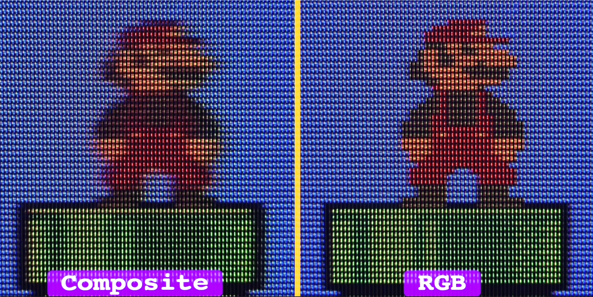
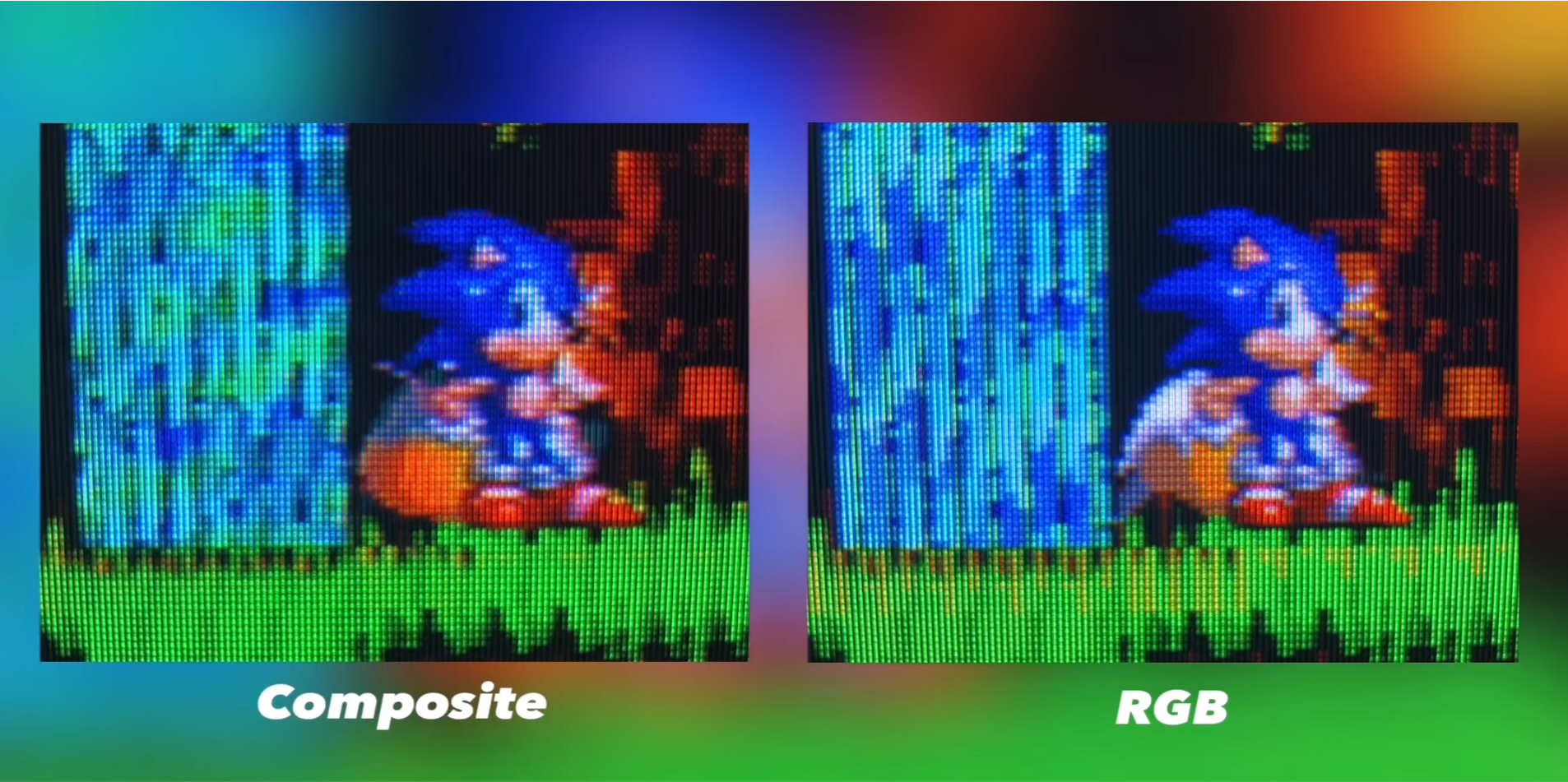
Here are some results of RGB mods versus factory composite video:
An RGB-modded TV, or a component CRT with an RGB transcoder can be a budget-friendly alternative to expensive professional monitors. While RGB isn’t for everyone, use the signal format of your choice.