I’ve recently seen a few devices that all use a similar PCB to adjust the horizontal and vertical position of an RGBs output. I believe it was originally designed for arcade machines that don’t have easy-to-access controls, such as my MiniMVS. I purchased a JAMMA version to test and it seemed to work exactly as advertised: Whenever I wanted to connect a different arcade board, I’d also connect this device and could easily center the image without touching the chassis controls. As a result, when I switched back to the MV1C, I didn’t need to re-calibrate anything, as the only changes made were on the external board.
The store I bought it from, Time Harvest, also had a version that accepts the lower voltage RGBs signals you’d find in consumer-grade equipment like classic game consoles. I was curious how it performed, as there are many more factors involved with SCART equipment and unlike most arcade setups, there’s a lot of potential for damage to be done. I was able to borrow one and while the unit I tested had issues, it might just be a defective one. If that’s the case, this could be an interesting device for people’s setups:
JAMMA Version: https://www.aliexpress.com/item/4001055931745.html
SCART / RCA Version: https://www.aliexpress.com/item/4001070254969.html
To test the SCART / RCA version, I first measured a console connected directly to an oscilloscope as a baseline measurement. I then measured the RGB levels when connecting the same console through the Picture Adjust box and the readings were identical. I suspected that the box is just passing the RGB signals and only processing sync, but to confirm, I tested dual-output. As you can see in the picture below (click all pictures for full-sized), the voltage (BY-AY) is basically halved:
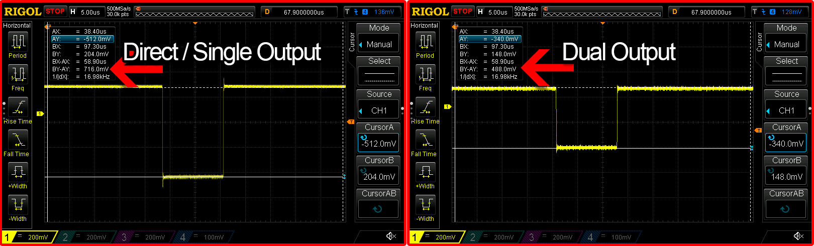
That proves both that the device is just passing through RGB and that it can NOT be used for dual-output! I don’t think Time Harvest advertises dual-output as a feature anyway, but I wanted to make the clear point: Use ONE input and ONE output at a time. Period. It’s nice that both SCART and RCA connectors are an option, but only one of each should be connected at a time, even if the second device is off!
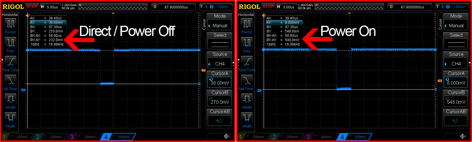
So, now onto sync testing. As with RGB, sync just passes through when it’s off and dual output is not supported. When powered on, I saw it react a bit differently:
When I tested the first console – An N64 with a Voultar RGB board – it seemed to double the voltage when powered on from 232mV to 540mV:
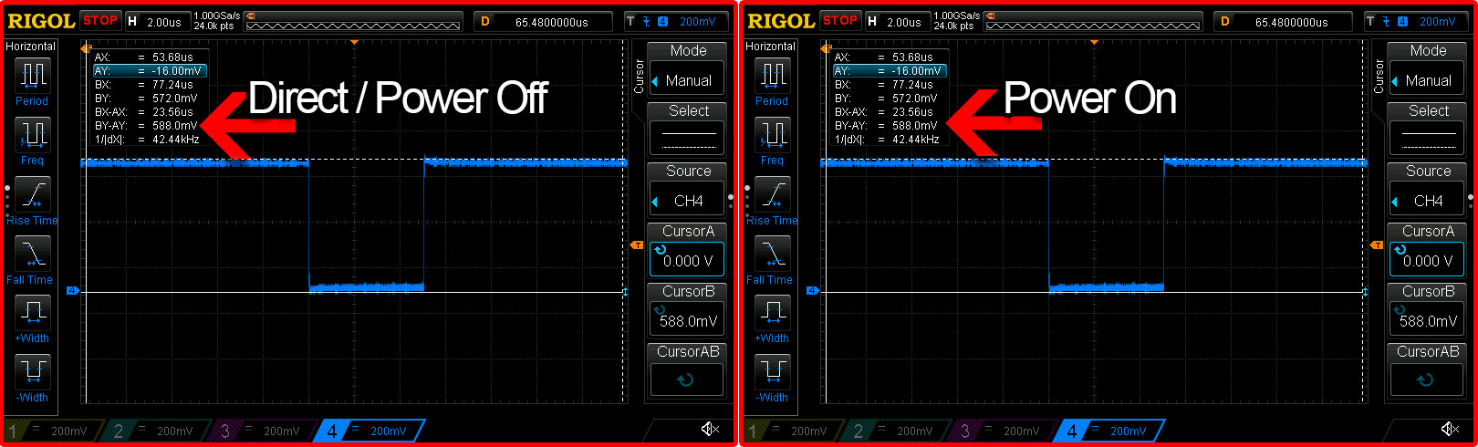
That’s still well under the maximum safe voltage, but I was concerned about what would happen with a higher voltage source. I connected a SNES – Also with a Voultar RGB bypass – and tested again. The voltage was identical in both modes:
I wanted to make sure this wouldn’t be a situation like others I’ve tested where voltage could spike if there were two sync strippers in line, so I connected the exact same SNES to two different SCART switches, each with sync stripping/regeneration turned on. Luckily, the voltage stayed the same:
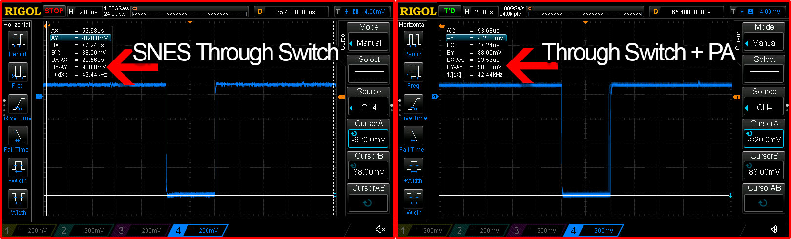
So, it doesn’t seem like there’s any safety issue with this Picture Adjust box, but I don’t want to say “definitely”, as I only tested a handful of scenarios.
One problem I did run into on all consoles, was the Picture Adjust box kept loosing sync. I spoke to other people who purchased that one and they don’t have any issues, so maybe there’s a problem with this particular one? I decided to take a closer look at the device itself:
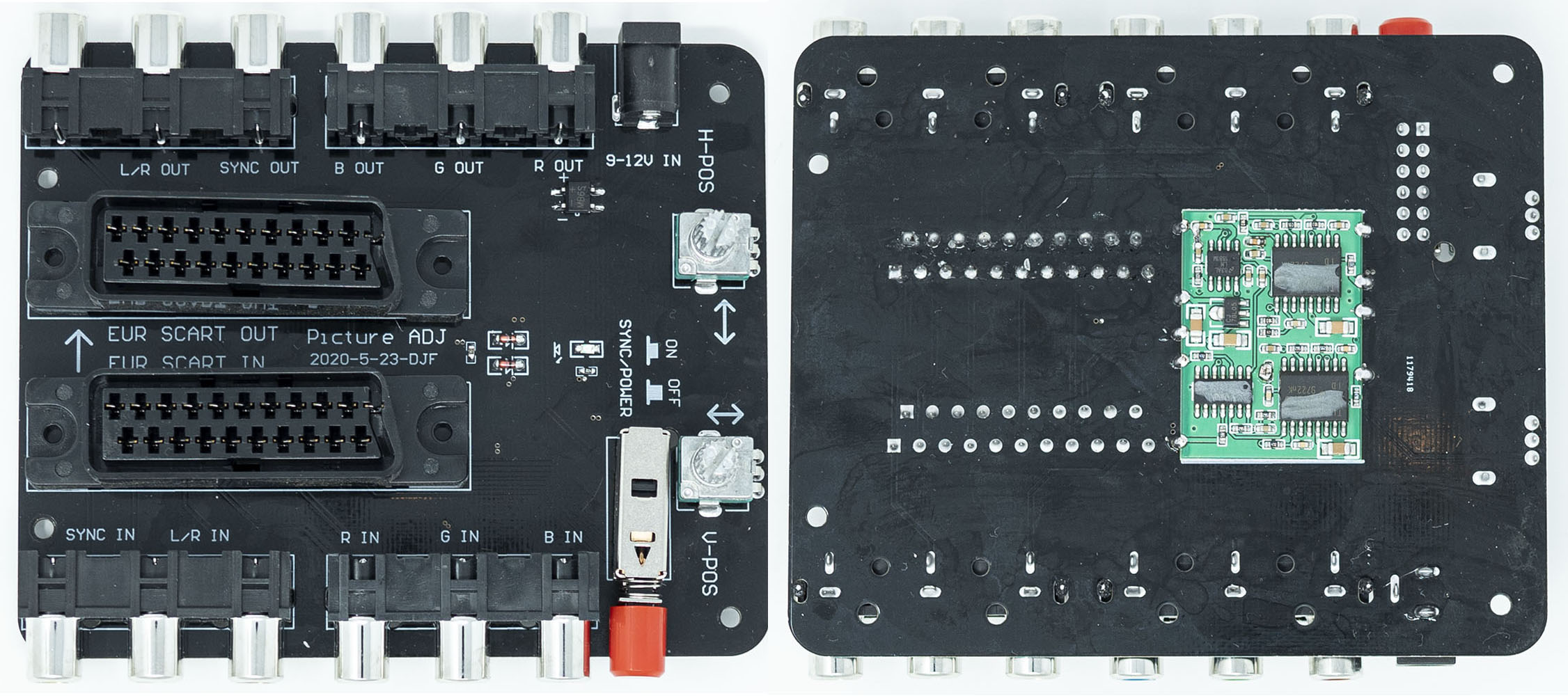
The whole thing is very basic and everything is routed through that board on the bottom. As mentioned before, it seems to be the same one used on their JAMMA version:
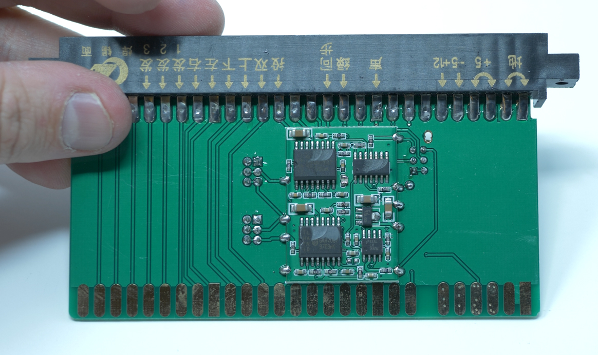
Here’s a closeup of the one used in the SCART version and below it is the one on the JAMMA version:
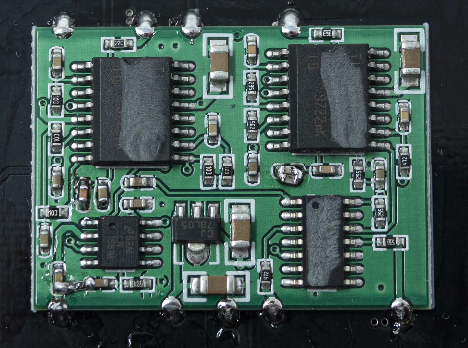
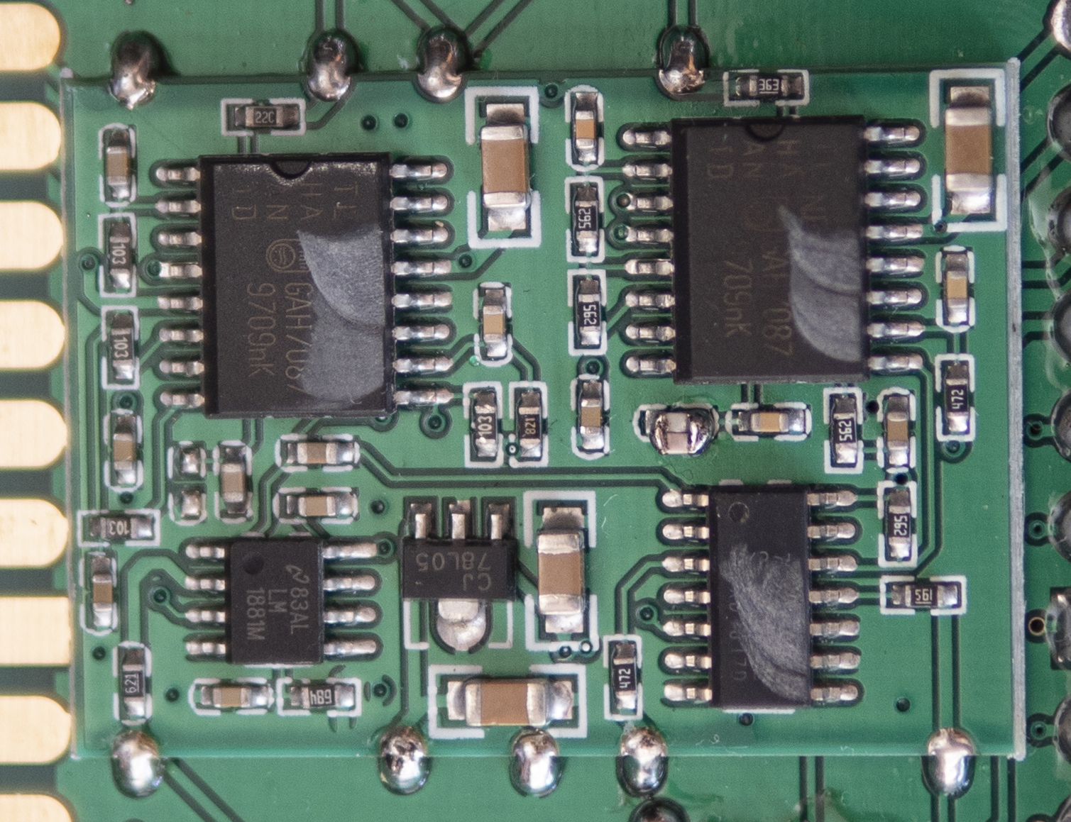
If you click on both of those pictures and flip between them both when zoomed to 100%, you’ll notice a few key things:
- The JAMMA board is missing a capacitor (although seems to work fine)
- The SCART board has a cap in place of a resistor…and then another resistor connecting that cap to another near the LM1881.
- Both have the poorly-manufactured “double cap” in the middle.
- All other components are the same.
While I’m not sure what the issue is with this box, it could be as simple as a poorly manufactured board and some of the bodges certainly show that as a possibility. If I had more time, I could probably re-flow the entire thing and maybe even replace the bodges with components to match the JAMMA board and re-measure. I think that’s really up to Time Harvest to troubleshoot though, not me.
Overall, these Picture Adjust devices seem okay to use. I’d recommend them for JAMMA use and assuming this is just a defective SCART version (and others work fine), it should also be okay to use with RGB monitors. I’d be cautious about using anything on SCART equipment like switches and scalers, but based on my testing it should be safe. If you have the ability to test yours, I’d always suggest that, even just for peace of mind.
I do think there’s room for more features though. I mean, you can get something like the Axunworks SCA-101, but that might be too feature filled. Hopefully we’ll someday see a box like this that can also filter the signal, support dual-output and maybe a JAMMA version that also adjusts RGB voltage.
Also, the circuit itself looks very similar to one Tim Worthington posted on his site a long time ago, so if you’re looking to design your own, maybe start there?:
Tim’s circuit: http://members.optushome.com.au/eviltim/other/other.htm
Board available based on it: https://oshpark.com/shared_projects/F90tGUDC
Case for the board: https://www.ebay.com/itm/163244317055