GBA RGB Mod
This mod shows you how to modify the Innovation TV-out adapter to output RGB. Please keep in mind that this adapter only outputs interlaced 480i, not progressive 240p. If you’ve gone through the trouble of installing this adapter, the RGB mod is worth doing, but I wanted to warn you in advance what to expect. Before you start this guide, please make sure your Game Boy Advance is properly working both by itself and with the Innovation TV adapter. If not, check out the main GBA page for help and more information. If your modded GBA is in good working order, you can now move along to modifying for RGB!!
– First, disassemble the TV adapter and locate the video pins: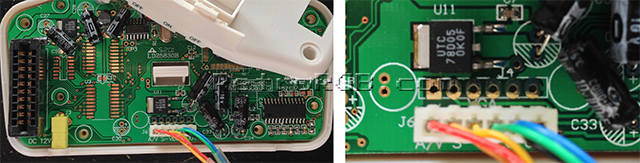
– Then, cut the cables from the existing wiring harness and solder them to the following pins (try to match the colors, as it will be easier on the other end of the cable). As a note, the “L” & “R” audio channels are optional, since you can just use the headphone jack on the GBA…more on that in a second:

The sync (S) is actually the composite video out. I’ve seen other diagrams floating around the internet that say you should hook sync to a different pin, but that never worked for me (I’ve done a few of these).
Segasonicfan emailed me with a great find though: There seems to be a Sony CXA chip (or clone) in this unit. You can get csync from the “sync-in” pin circled below. Please note that this is 5v TTL CSync, so it may not be compatible with some SCART TV’s expecting 1v p-p Sync. You can probably pull RGB directly from that chip as well, but the solder points listed above are a bit easier to solder to. Click on the picture for a full-sized view:

– Once you’ve soldered the video pins, you can decide if you’d like to pull audio directly from the board , or separately from the headphone-out of the GBA. If you wanted to pull audio from the board like I did, you’ll need to add another cable to the stock one, as there won’t be enough for everything. Also, I decided to remove the connector that was on the board, but it’s probably easier to just leave it in there:

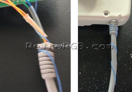
– I used two thin pieces of cable to add a second audio channel instead of one thick one, so it would be easier to manage. I just twisted them around the entire length of the cable (as pictured below) and they seem to stay together fine. Also, the thin cable was able to wrap around the notch in the cable, so it fit perfectly when the case was bolted back together:
– Cut the other end of the cable at the connection point towards the end:

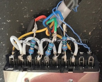
At this point, you need to solder the wires into a connector. Most people use SCART for RGB, but you can use anything you’d like. I used a spare Wii SCART cable I had laying around that only cost $5, but anything will do.
When you solder the cables, you’ll need to add a 75 Ohm resistor to each of the color cables. Just solder a resistor directly to the R-G-B, pins 15, 11, 7 (respectively) and then solder the cables to the resistors. Since I used a Wii SCART cable, there were capacitors where the resistors should be. I de-soldered them and replaced them with the resistors and it worked great. I’m not sure if it would be better to leave the capacitors on or not, but mine have worked perfectly without them. Here are the resistors I used:
http://www.digikey.com/product-detail/en/MRS25000C7509FRP00/PPC75.0ZCT-ND/595092

After that, follow the basic SCART diagram, wiring SYNC to pin 20 and L/R audio to pins 6 and 2 (respectively). Also, the Wii SCART cable I used already had ground soldered to all the necessary pins, so I just connected ground to one of them. If you’re building the connector from scratch, you’ll probably need to make little jumpers like in this picture:
One last thing: The Wii SCART cable had a wire with a 75 ohm resistor connecting pins 8 and 16. If you use a SCART cable that already has it in there, just leave it in. If not, you’ll only need it if you’re using a PAL TV; RGB monitors and upscalers shouldn’t need this at all. If I’m wrong, please let me know, but I’m 99% sure I’m right…
After that, put the SCART connector back together and give it a try!
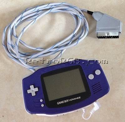
So, that’s it. Check out the finished product:
Now that you’re done, feel free to go back to the main GBA page. If you’d like info on mods for other systems, head to the Getting RGB From Each System page or check out the main page for more retro-awesomeness.