About once a month, I’ll send a message to Ste asking him: “Hey, if I plug your cables into this new device, will the voltage be okay? I measured on the scope at X volts.”
…and every time, he’d respond saying he “doesn’t have enough information to answer that”, throwing adult words at me like “thevenin”. It took some verbal lashings, but Ste eventually drove the point home that voltage will change based upon resistance on the line and was nice enough to explain it to me. Let’s walk through what he taught me:
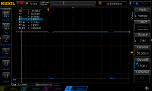
To start this experiment, Ste asked me to take two scope plots: One of SNES csync properly measured with a 75ohm termination on the signal and one without the termination (click on any picture in this post for a full-sized view):
First, measuring with no termination reads 2.45v:

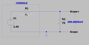
With 75ohm termination (a typical “RGB” environment), it reads 380mV (or 0.380v):

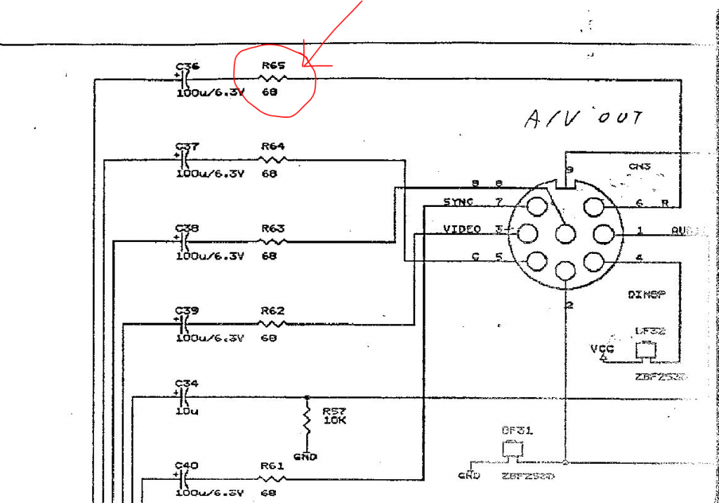
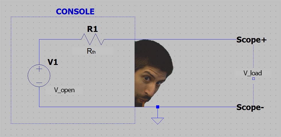
So in this scenario, I have basic measurements from the console, but have no idea what’s the actual circuit that drives the output. Measuring without a load gets 2.45v, which to start would be represented as:
Now, I can approximate what’s in the unknown box using something called “Thevenin’s Theorem”. What this says is that you can reduce almost anything (under certain assumptions…see bottom of post for more info) into a voltage source with a series resistor. So, you get this:
Now, in this example, we already know what Vth is (under V1 in the above pic), because we got it by measuring the output without a load:
Since we’re working with analog video, I can easily get Rth by measuring with a typical 75ohm load, as we did in the second measurement that read 380mV (0.380v):
Now we can use the Thevenin theorem to complete the circuit and get the unknown resistance, using the following equation:
So, this stuff can be confusing and if you haven’t done math in awhile, this might all look like hieroglyphics to you. Let me walk you through it…and by walk you through it, what I’m really saying is ‘let me leave myself an idiot-proof note for when I need to reference this page later’ 🙂
Let’s start with the formula and populate it with the numbers from this example: Rth=[(V-open/V_load)-1]*Rload would end up being Rth=[(2.45/0.38)-1]*75, as we measured 2.45 with no load (V_open), 0.38 under a 75 ohm load (V_Load)…which also means “Rload” would be 75.
Now we start by completing the first equation in the brackets: 2.45 divided by 0.38, which equals 6.447368421052632. All we need for video is the first few decimals, so let’s call this 6.44736 (you can probably use only two or three decimals, but roll with this).
That would make the equation now look like this: Rth=[6.44736-1]*75
Then complete the next equation inside the brackets: 6.44736 minus 1, which equals 5.44736. Now we have: Rth=5.44736*75 (you can remove the brackets since the operation inside is complete), which is simply 5.44736 times 75. That results in the number 408.552, which is Rth.
So, to conclude, Rth=408.552
We can now see that my original question of “is x voltage too high?” is impossible to answer without factoring in the resistance on the line…and it was ignorant to assume that any solution other than a basic RGB monitor would always have a 75ohm load. BUT, now that we have the Thevenin equivalent resistance (without cheating), we were able to calculate the true answer to my question, by factoring in the input termination resistance of the video circuit we’re analyzing:
To let Ste explain it in a higher-level of abstraction:
You can’t predict anything with 1 data point, but if you get 2 points you can draw a straight line between and through them and then you can predict any situation by picking any other point on that line. That’s really what you’re doing here. So, if you want to get more useful data when doing your measurements, then you should take two measurements, one with load and one without.
This is one of the most useful tools in electronics.


So, what did we learn from all of this? For me personally, it was multiple things, in this exact order:
- Don’t ever ask Ste a question unless you really want to know the answer.
- It was very dangerous of me to assume my single-point measurements were telling the whole story.
- My ignorance was a perfect example of why so many hobbyist’s circuits can be wrong and possibly harmful.
- This stuff is complicated. The more I learn, the more I realize how little I actually know. That’s why we need Master Ste to teach us.
For more information on using Oscilloscopes and the basics on getting started, please see the scope page: https://www.retrorgb.com/oscilloscope.html
Auto Amazon Links: No products found. http_request_failed: A valid URL was not provided. URL: https://ws-na.amazon-adsystem.com/widgets/q?SearchIndex=All&multipageStart=0&multipageCount=20&Operation=GetResults&Keywords=B07D57VV5Z|B012938E76&InstanceId=0&TemplateId=MobileSearchResults&ServiceVersion=20070822&MarketPlace=US Cache: AAL_466269801b01b0aeb9067e76a9375047
Final note from Ste:
This method only works when what is in the unknown box is a “linear” circuit, hence the drawing a line between two points analogy. For many circuits this happens to be true, or can at least be approximated as such, so it’s common to make this assumption. There are other situations where it can’t be used or you need to pick different points which represent specific conditions where the circuit is linear. One example of this would be the open-collector TTL logic output of a stock Genesis CSYNC output, and the further complications of adding a capacitor in series to that output.


